
SmartLink Wall Switch Module - FB

PRODUCTS
Specification
Technical Data
| Model | AGD-RD144RB1 | |
|---|---|---|
| Input/DALI | Voltage | DALI bus standard |
| Current | 20mA with 4 indicators on, 4mA with indicators off | |
| Startup Time | 1 second | |
| Controls | Button | Dry switch x4, common high |
| Indicator | Single LED per channel, max 5mA, common high 4V | |
| Environment | Temperature | Ta: -30...+50℃ |
| Humidity | 20...95% | |
| Storage | -40...+80℃, 10...95% | |
| Dimming | DALI | IEC 62386 101, 103, 301, 332 |
| Feedback | Mono color, dimmable | |
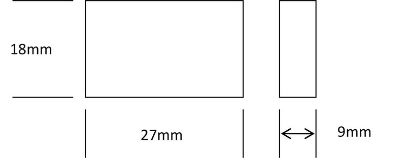
| Others | Dimension | 27*18*9mm |
| Weight | ||
Dimension
Installation
Wiring and circuit diagram
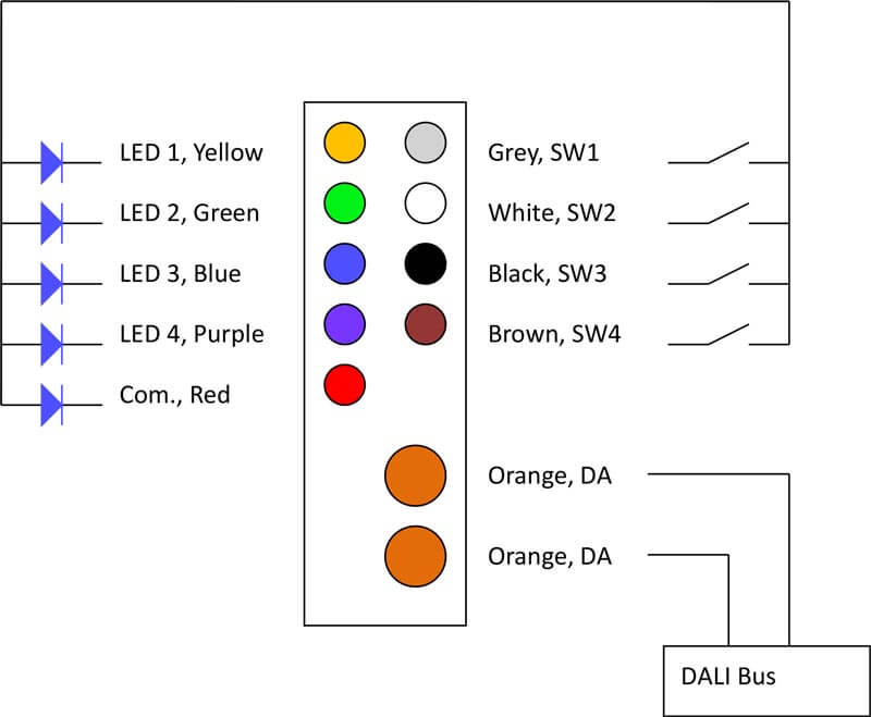
- Switch buttons and indicators are sharing their common high. The common high voltage can be 4~5V.
- Each indicator and button must be its pair order. DALI feedback function is to each button as a pair.
- Do not inject any power source to the button and indicator pins.
- All wiring is recommended to be done with main power source is off.
- DA/DA wires are for DALI bus wires, and they are cataloged FELV, and should be connected to FELV circuit.
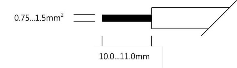
Wiring cable and cross section
The cable cross-section of each terminal can be 0.75...2.5mm2, and the wire preparation length can be10.0…11.0mm. Each terminal should be used one wire only.
Hot plug-in
Hot plug-in may be done with protective gloves. But, it is recommended to remove its power before installation, wiring and repairing.
Usage and install
The converter is designed for converting existing wall-switches to be a DALI wall-switches, and benefit both advantages.